Engineers/The drawing office
The drawing office
Before a blade was cut or a hinge pinned, the argument was conducted on paper — and that paper is how we know how the rotor problem was actually solved.
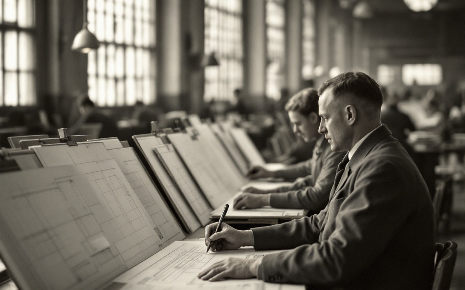
Where the argument happenedBoards in rows under high windows: rotor work is geometry before it is anything else.
Geometry First
Rotor work begins with geometry. A blade sweeping through air is an aerofoil in constant angular motion, and the forces acting on it — lift, drag, centrifugal loading — shift with every degree of rotation. To reason about that, you need to draw it: plan views of the disc, chord sections at multiple stations along the blade, hinge offsets dimensioned to tolerances tight enough to matter. The drawing office was where that reasoning became precise enough to build from.
Juan de la Cierva worked through successive machines across the 1920s by iterating on exactly these drawings. The dissymmetry of lift problem — the advancing blade producing more lift than the retreating one — was not obvious from the air. It was visible in the geometry, once you had drawn out the velocity that each blade station encountered at each azimuth angle. The solution, the flapping hinge, was equally a drawn solution: a pivot placed at a calculated offset from the rotor hub, sized to allow the blade to rise and fall through an arc small enough to be structurally manageable and large enough to equalise lift across the disc.
Geometry firstRotor design was argued on paper before it was flown; the drawing carries the dimensions that mattered.
What that required in the drawing office was not just skill at the board but a particular discipline: the ability to hold the whole rotating system in mind while drawing a single component, because every dimension had a consequence somewhere else on the disc.
How the Work Was Done
Spanish aeronautical drawing offices of the interwar period worked in the way all precision engineering drawing offices worked: paper on inclined boards, ruling pens and compass sets, scale rules and set squares, ink applied with a steadiness that came only from practice. Drawings were made to scale — typically 1:5 or 1:10 for assemblies, 1:1 for critical joints — and reproduced by blueprint or diazo print ↗ for the workshop floor. The original stayed in the office, filed in a numbering system that had to be rigorous because a superseded drawing reaching the jigs was how you built the wrong thing.
At the facilities that grew around early Spanish aeronautical work — at Cuatro Vientos outside Madrid, at Getafe, at the workshops that would eventually consolidate into CASA ↗ — the drawing office was a distinct space with its own hierarchy. A chief draughtsman or engineer oversaw the sheet numbering and revision system. Detail draughtsmen handled individual parts. The engineer who had worked out the geometry checked dimensions against calculation before the sheet was released. When a blade geometry was revised after a test flight — after something had flexed differently than predicted, or a hinge had loaded unevenly — the change went back to the drawing office, where the delta between the old sheet and the new one was reasoned out before anyone picked up a chisel.
Emilio Herrera Linares, an engineer and officer with deep involvement in early Spanish aeronautics, understood this discipline in the wider context of precision engineering and scientific draughtsmanship. The drawing was not a picture of an idea; it was a specification that the workshop was contractually obligated to follow. Every tolerance, every material callout, every surface finish note carried engineering intent.
The other half of the collectionFlat drawers of large drawings: the reasoning behind the hardware is on paper.
What the Archives Hold
The drawings that survive are the primary source for understanding how the rotor was actually solved. Where a test report tells you that a machine flew better, a drawing from the same period tells you what was changed and by how much. Hinge offsets can be measured. Blade chord profiles can be compared across marks. The physical objects — the machines held today at the Museo del Aire — are the end product; the drawings are the argument that produced them.
That argument was conducted by people who could not compute a rotor in the modern sense: no finite-element analysis, no computational fluid dynamics. What they had was classical thin-aerofoil theory ↗, trigonometry, and the discipline to follow the geometry wherever it led. The drawing office was the instrument through which that discipline was applied, and the sheets it produced are, in the most literal sense, where the thinking is.