Rotorcraft/The flapping hinge
The flapping hinge
On a rotor moving forward the advancing blade meets far more airflow than the retreating one; letting each blade hinge freely up and down is what stopped the resulting roll from wrecking the machine.
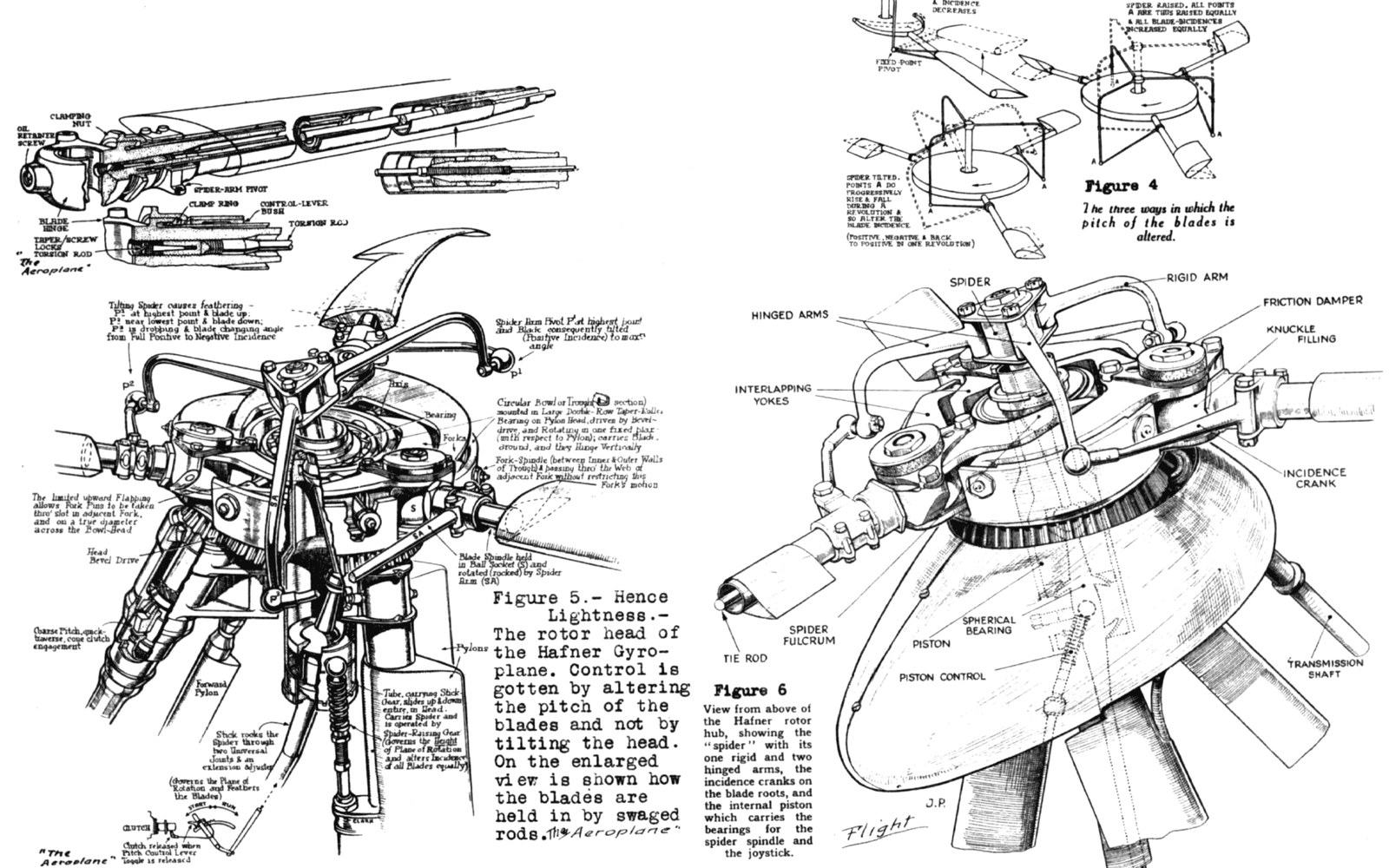
The pinned jointThe hinge sits between blade and hub, and on surviving machines it can still be moved by hand.
The blade that wanted to kill the machine
Every rotor blade generates lift proportional to the square of the airspeed it sees. On a hovering machine, every blade sees the same wind — whatever velocity the rotor itself creates — so lift is symmetric and the disc stays level. Add forward speed and that balance collapses. The blade sweeping forward into the oncoming air — the advancing blade — sees its own rotational velocity added to the aircraft's forward speed. The blade sweeping rearward — the retreating blade — sees those same velocities subtracted. Because lift scales with the square of velocity, the difference across the disc can be enormous even at modest forward speeds. The result is a violent rolling moment toward the retreating side, and if nothing absorbs it, that moment rolls the machine over.
This is dissymmetry of lift: not an edge case, not a subtle trim problem, but the central structural fact of a rotor in forward flight. Juan de la Cierva understood it clearly from his earliest attempts at a rotary-wing machine. What he worked out — in Madrid, at Cuatro Vientos, through a sequence of machines that failed and then did not fail — was a mechanical answer so simple it is almost disgusting: let each blade hinge freely at the root so it can rise and fall independent of its neighbours.
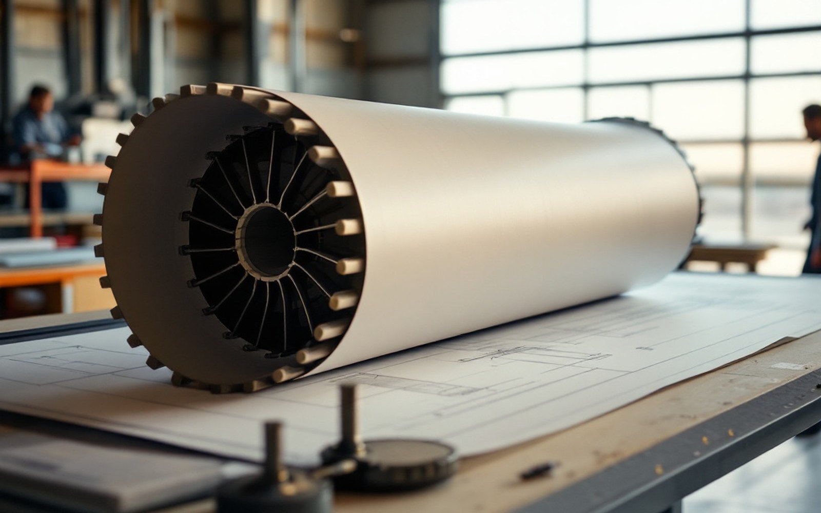
Geometry firstRotor design was argued on paper before it was flown; the drawing carries the dimensions that mattered.
The logic is precise. If the advancing blade generates excess lift, it begins to rise. As it rises, the geometric angle at which it meets the airflow decreases — the blade's own upward movement tilts the relative airflow against it, reducing its angle of attack. Lift therefore falls back toward equilibrium. On the retreating side the blade sinks, its angle of attack increases, and lift is restored. The rotor disc tilts slightly — it cones, the tips describing a shallow inverted bowl rather than a flat plane — but no sustained rolling moment reaches the fuselage. The flapping hinge converts an aerodynamic asymmetry into a controlled mechanical oscillation and then lets the oscillation dissipate.
What the hinge actually is
Mechanically, a flapping hinge is a pivot mounted close to the rotor hub — historically a literal pin or bolt, oriented roughly parallel to the leading edge of the blade — around which the blade is free to rotate in the plane containing the rotor shaft. It does not let the blade swing sideways (that is the drag hinge's job) and it does not change the blade's pitch (that belongs to the pitch-change bearing). Each function requires its own degree of freedom, and conflating them in description, let alone in hardware, is how confusion begins.
On de la Cierva's earliest attempts — machines designated C.1 and C.2, built in the early 1920s and both unsuccessful — the rotor blades were attached rigidly to the hub. The aerodynamic forces those configurations produced made controlled flight impossible. The C.4, flown at Getafe in January 1923, introduced freely hinged blades and flewsuccessfully. Not a tentative hop — a demonstrable, repeatable flight, the first by a practical rotorcraft. The hinge is why.
The engineering is not quite as frictionless as the concept. A blade left to flap with no restoring moment at all would flap to angles that destroy the geometry of the disc, so early designs introduced coning stops — physical limits on how far up a blade could rise — and carefully balanced blade mass so that centrifugal force, acting on the blade as it rotates, provided a strong natural restoring tendency. At operating rotor speed, centrifugal stiffness dominates: the blade wants to fly outward in the plane of rotation, and that tendency acts as a powerful spring, limiting flap to a few degrees either side of the nominal coning angle. The pivot does not need to carry large bending loads, which is precisely the point — bending loads that would otherwise crack a rigid attachment ↗ are replaced by a small, controlled rotation around the hinge pin.
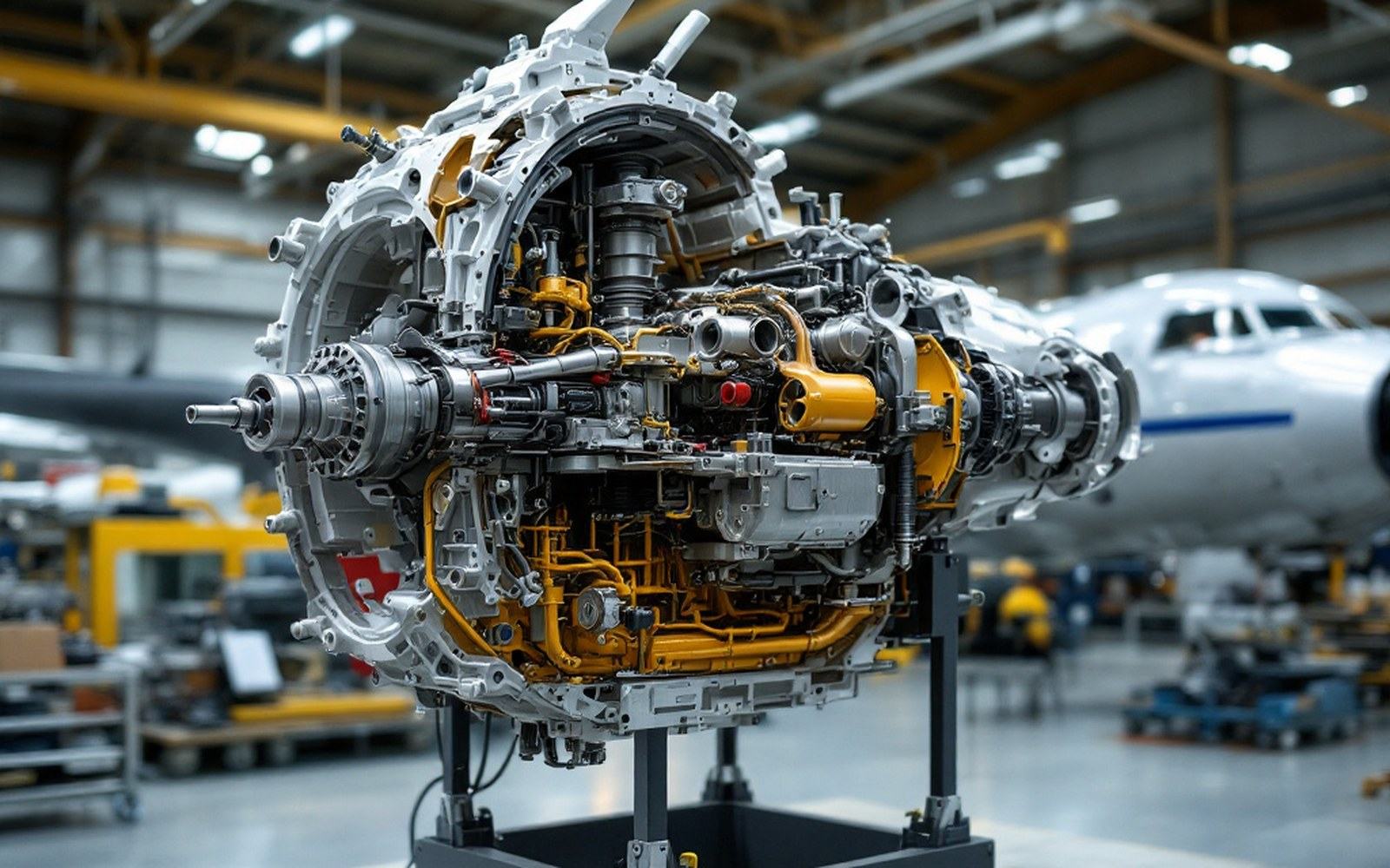
Sectioned to be understoodA cut-away assembly explains in one look what a page of description struggles with.
Manufacturing the hinge required precision that was demanding for the period. The pin and its bearings had to sustain high centrifugal tensile loads while allowing rotation with minimal friction — stiction in the bearing would mean the blade couldn't flap freely at the low speeds where the asymmetry is worst and the restoring centrifugal force is smallest. Early C-series autogiros used bronze bushings running on steel pins, assembled in a hub forged or machined from steel, and the tolerances involved pushed Spanish workshop practice of the early 1920s close to its limits. The drawings from those designs — some held in archives associated with what is now the Museo del Aire — show the hinge geometry worked out with a care that makes clear de la Cierva and his collaborators knew exactly which dimension mattered and why.
From autogiro hub to helicopter rotor
The flapping hinge solved the problem for the autogiro because the autogiro's rotor, unpowered in flight and driven only by the passing airflow through autorotation, imposes relatively gentle and predictable loads on its hub. The retreating-blade problem exists, the flapping hinge eliminates it, and the machine flies.
The helicopter is a harder case. Its rotor must transmit torque from the engine to the blades while simultaneously allowing each blade to flap. Early helicopter designers working in the 1930s and 1940s — in several countries, some of them building directly on de la Cierva's patents and publications — carried the flapping hinge concept forward but had to solve the interaction between torque transmission and flap freedom. One answer was the fully articulated hub, in which flapping hinges, drag hinges and pitch-change bearings are all present and mechanically independent. Another, developed later, was to build enough structural flexibility into the blade root that a discrete hinge pin could be eliminated entirely — the hingeless rotor, where elastic bending in the root material does the same job the pin did.
Both paths trace back to the same insight: the blade must be free to find its own lift equilibrium as it sweeps through asymmetric air. The Royal Aeronautical Society ↗, which granted de la Cierva a fellowship in recognition of this work, placed the flapping hinge among the fundamental contributions to aeronautical engineering — not because it is complicated, but because recognising the problem and finding a mechanical answer of such economy required the kind of thinking that happens once, and then becomes obvious in retrospect.
Still in useLow hangars and a wide apron on the southern edge of Madrid, where the first practicable rotorcraft flew.
The surviving autogiros in the Museo del Aire collection at Cuatro Vientos allow the hinge to be seen in hardware, not only in diagrams. It is a small thing — a pinned joint, a drilled flange, a few centimetres of steel — sitting between the blade and the hub, carrying perhaps thirty years of consequential engineering on its shoulders.