The Collection/Rotor-head cutaways
Rotor-head cutaways
A sectioned assembly explains in one look what a page of text struggles with.
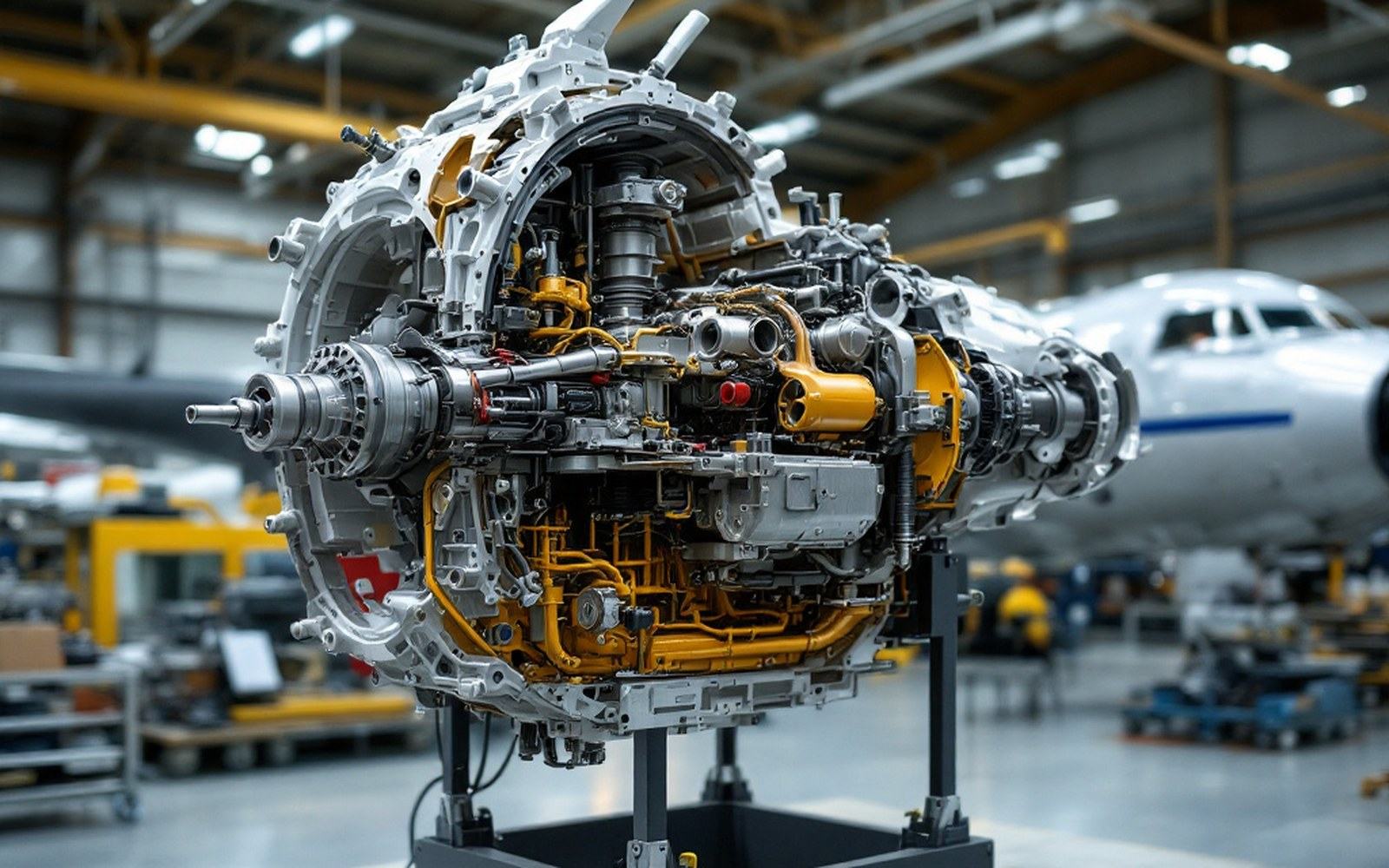
Sectioned to be understoodA cut-away assembly explains in one look what a page of description struggles with.
The machine opened up so the problem becomes visible
A sectioned rotor head tells you more in thirty seconds than a page of kinematic text. Every hinge, every bearing, every pitch-change rod sits where you can trace it from input to effect — cause and consequence laid out in metal rather than prose.
The Museo del Aire holds the most important surviving examples from the Spanish autogiro programme, and among its lesser-celebrated holdings are several cutaway and sectioned assemblies that show the rotor-head internals in detail. They were made for instruction and for demonstration, which makes them invaluable documents: they preserve configurations that the flying machines themselves no longer carry, because most airworthy heads were rebuilt, modified or scrapped when a new design superseded them.
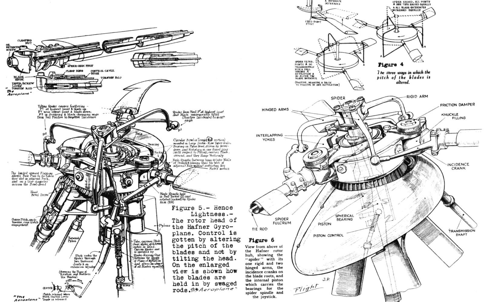
The pinned jointThe hinge sits between blade and hub, and on surviving machines it can still be moved by hand.
Photo: Hafner AR.III rotor head detail NACA-AC-205 · Wikimedia CommonsWhat the cutaway reveals
Start at the hub. The blades of an autogiro rotor do not attach rigidly to the shaft. Each one is joined through a flapping hinge — a pivot that lets the blade rise and fall in the vertical plane with each revolution. Without it, the asymmetry between the advancing and retreating sides of the disc would impose a rolling moment so large that the machine could not be controlled. Juan de la Cierva ↗ identified this as the central problem after his early fixed-blade designs departed the ground and immediately rolled. The hinge was the fix, and a cutaway shows you precisely where it sits in the assembly and how much angular freedom it allows.
Outboard of the flapping hinge, many heads carry a drag hinge — a second pivot, this one in the plane of rotation, that lets the blade swing fore and aft as its lift and drag loads vary during the cycle. A cutaway shows the small damper fitted across this hinge: a device that absorbs energy and prevents the blade from oscillating into a destructive resonance called ground resonance. Without the damper, the geometry is visible but incomplete; the sectioned examples in the national collection preserve the damper housing even where the damper itself has been removed, so the function can still be read.
Above the hinges sits the pitch-change mechanism. On early Cierva designs the blade pitch was fixed, relying entirely on autorotation to keep the disc turning in unpowered descent. Later configurations introduced collective pitch change — a mechanism that raises or lowers all blades simultaneously and, in the jump take-off variants, was used to store energy in the rotor before a rapid pitch increase flung the machine into the air. The pitch-change rod and its connections to the swashplate ↗are among the most spatially complex elements in any rotorcraft head, and the cutaway is the only practical way to show how a single axial input fans out into simultaneous, equal deflection at every blade root.
The bearings deserve attention too. Rotor heads run continuously at comparatively low speed but under highly variable load, and the bearing specification — races, retainers, lubrication passages — changed substantially as operating experience accumulated. Where the cutaway preserves original bearings rather than replacements, the design generation can be dated from the bearing alone.
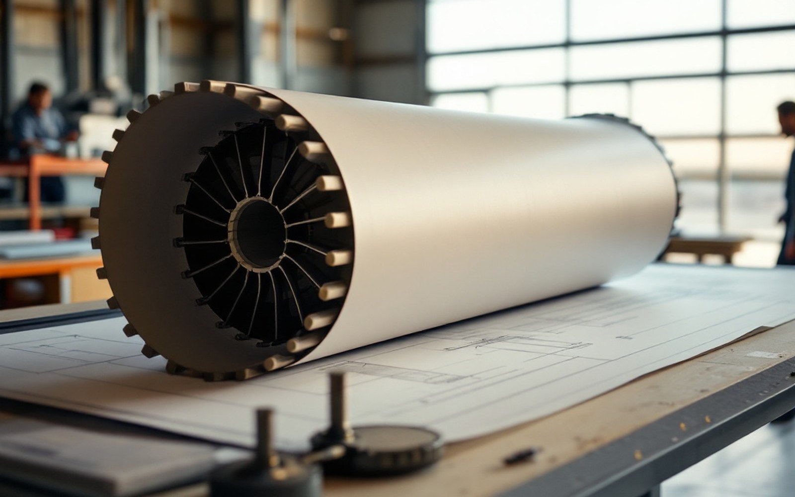
Geometry firstRotor design was argued on paper before it was flown; the drawing carries the dimensions that mattered.
Reading the assembly as a document
A cutaway is an argument in hardware. The choices visible in it — where the hinge axis falls relative to the blade's centre of pressure, how much offset is built into the flapping geometry, which elements are adjustable and which are fixed — reflect the state of rotorcraft understanding at the moment the head was designed. The drawings and archives at the Museo del Aire often allow cross-referencing: a sectioned head beside a surviving general-arrangement drawing is as close as the collection comes to a complete engineering record.
Anyone willing to spend time with these assemblies, and to read them rather than simply look at them, will understand the dissymmetry problem and its solutions more solidly than any textbook provides.